Some situations arise where the signal of interest is corrupted by interference. A common example is air-to-ground communications. Consider the environment of a helicopter cockpit. Within the cockpit, audible noise is produced by the wind, the helicopter engine, and the pilot’s voice. In this case, the signal of interest is the pilot’s voice but this signal may be overwhelmed by the other noise sources. Simply creating a band-pass filter around the frequencies that lie within the human vocal range is insufficient to recover the signal of interest because the engine and wind interference may occupy the same frequencies. A better approach is to use an active noise cancellation system.
A noise canceling system requires two or more sensors, a primary sensor to measure the corrupted signal of interest and secondary sensors to measure the interference. It is important that the sensors measuring the interference be placed somewhere where it is possible to measure the interference but not the signal of interest. At this point, many assume that canceling the interference is simply a process of subtracting the interference measured at the secondary sensors from the signal containing both the desired signal and interference. In most cases, this approach fails or achieves little improvement. This is because the primary sensor rarely measures the interference with the exact same amplitude, phase, and distortion as the secondary sensors.
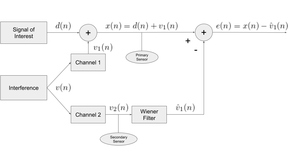
Going back to our helicopter example, the primary sensor may be a microphone located directly in front of the pilot’s mouth. The secondary sensors must be placed somewhere within the cockpit where they pick up the interference (the wind and engine noise) without picking up the pilot’s voice. Being spatially separated means that the sensors measure the noise from the wind and engine with different propagation delays, amplitudes, and may experience different distortions. However, because the unwanted noise measured at the primary and secondary sensors is generated by the same processes, the noise information between the two sensors is highly correlated. Thus it is possible to design a Wiener filter that filters the noise measured at the secondary sensors and produces an estimate of the noise measured at the primary sensor. This noise estimate is subtracted from the corrupted signal to produce an estimate of the signal of interest. Figure 1 is a block diagram that illustrates this concept.

Post Notations
Before going on to the derivation, let’s define some notation so that we’re all on the same page. Let ![]() ,
, ![]() and
and ![]() represent the expectation operator, the estimate of
represent the expectation operator, the estimate of ![]() , and the autocorrelation function of
, and the autocorrelation function of ![]() respectively. The expectation operator returns the expected value or mean of a random variable. The estimate of
respectively. The expectation operator returns the expected value or mean of a random variable. The estimate of ![]() is found by filtering
is found by filtering ![]() with our Wiener filter as follows
with our Wiener filter as follows
![]()
where ![]() is the number of filter coefficients.
is the number of filter coefficients.
The autocorrelation function for a wide sense stationary (WSS) signal is defined as
![]() .
.
The cross-correlation function for jointly WSS signals is defined as
![]()
Let the error be defined as the difference between the desired signal and the estimate of the desired signal
![]()
and the MSE be defined as
![]() .
.
Finally, let ![]() represent the complex conjugate operator.
represent the complex conjugate operator.
Deriving the Noise-Canceling Wiener Filter
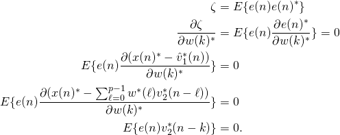
The object of the Wiener filter is to minimize the mean squared error of the signal (check out this related Wiener filter post). For this derivation, it is assumed that the signal of interest and the interference are jointly wide sense stationary. A signal is wide sense stationary if the signal has constant mean, the autocorrelation depends only on the lag, and the variance is finite. As defined in the above diagram the error is the corrupted signal minus the estimate of the interference. With this definition, we derive the noise-cancelling Wiener filter.

Now that the derivative is set to zero, we can solve for the filter coefficients that satisfy the equation.
![Rendered by QuickLaTeX.com \begin{align*}E\{[x(n)-\hat{v}_1(n)]v_2^*(n-k)\} &= 0 \nonumber \\E\{[x(n)-\sum_{\ell=0}^{p-1}w(\ell)v_2(n-\ell)]v_2^*(n-k )\}&=0 \nonumber\\E\{x(n)v_2^*(n-k) - \sum_{\ell=0}^{p-1}w(\ell)v_2(n-\ell)v_2^*(n-k)\} &= 0 \nonumber \\E\{(d(n)+v_1(n))v_2^*(n-k)\} - E\{\sum_{\ell=0}^{p-1}w(\ell)v_2(n-\ell)v_2^*(n-k)\} &=0 \nonumber\\\sum_{\ell=0}^{p-1}w(\ell)E\{v_2(n-\ell)v_2^*(n-k)\} = E\{d(n)v_2^*(n-k)\} + E\{v_1(n)v_2^*(n-k)\} \nonumber\\ \end{align*}](https://grittyengineer.com/wp-content/ql-cache/quicklatex.com-d4c978d9982b248f47a5ae706a8981d3_l3.png)
However, if we let the desired signal, ![]() and the noise interference
and the noise interference ![]() be uncorrelated (which in most cases is true) then
be uncorrelated (which in most cases is true) then ![]() and
and

Unfortunately, we don’t have a sensor that measures ![]() exclusively, we have a sensor that measures
exclusively, we have a sensor that measures ![]() which contains both the unwanted noise and the signal of interest. Basic algebra tells us that
which contains both the unwanted noise and the signal of interest. Basic algebra tells us that
![]()
Let’s see what happens when we substitute ![]() for
for ![]() for the cross correlation term.
for the cross correlation term.
![Rendered by QuickLaTeX.com \begin{align*} r_{v_1 v_2}(n) &=E\{v_1(n)v_2^*(n-k)\}\\ &= E\{[x(n)-d(n)]v_2^*(n-k)\} \\ &= E\{ x(n)v_2^*(n-k)-d(n)v_2^*(n-k)\} \\ &= E\{ x(n)v_2^*(n-k)\} -E\{d(n)v_2^*(n-k)\} \end{align*}](https://grittyengineer.com/wp-content/ql-cache/quicklatex.com-2c3f5d73f211b18dc1610525880e4df9_l3.png)
If the signal of interest is uncorrelated with ![]() (this should be true in most practical cases) then the term on the right goes to zero and
(this should be true in most practical cases) then the term on the right goes to zero and
![]()
This is much easier to work with because we have a sensor that records the signal ![]() .
.
Noise Canceling Example
To better illustrate noise canceling using the Wiener filter, I have added three audio files. The first audio file is the observed signal ![]() . In this example, the unwanted noise interference,
. In this example, the unwanted noise interference, ![]() , is a simple tone that should be clearly audible. The second audio file is after the unwanted signal,
, is a simple tone that should be clearly audible. The second audio file is after the unwanted signal, ![]() , has been estimated from
, has been estimated from ![]() and removed, leaving the desired audio recording. The final file shows what would happen if the signal recorded from the secondary sensor,
and removed, leaving the desired audio recording. The final file shows what would happen if the signal recorded from the secondary sensor, ![]() , was simply subtracted from
, was simply subtracted from ![]() .
.
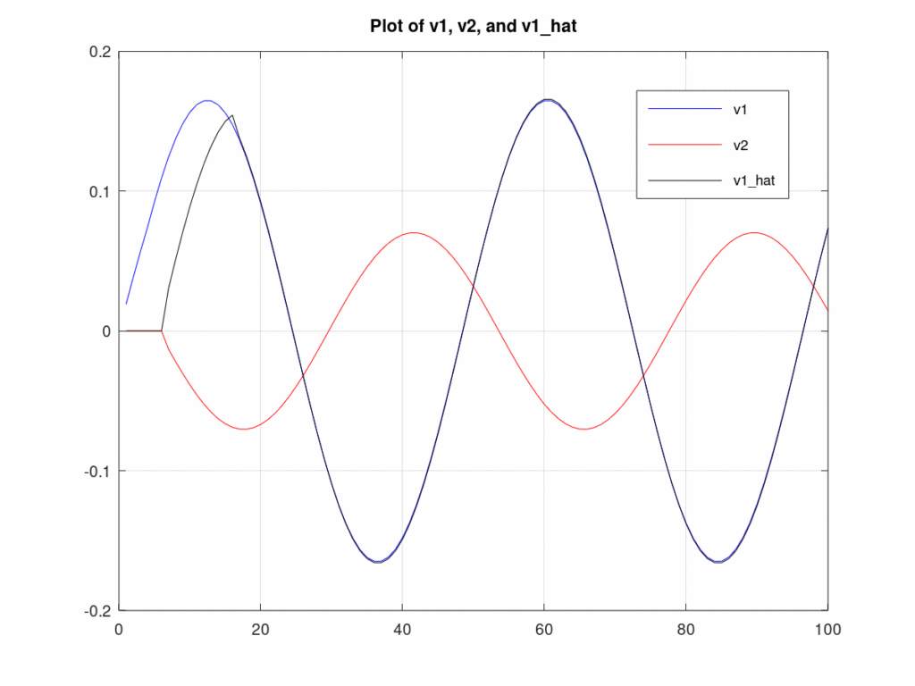
The pure tone was generated in simulation, thus we have access to it even though real applications would not. Plotting ![]() ,
, ![]() , and
, and ![]() can be helpful in understanding how the system works. Figure 2 plots these three signals. Notice that
can be helpful in understanding how the system works. Figure 2 plots these three signals. Notice that ![]() and
and ![]() are out of phase by nearly 180 degrees. It is now obvious why subtracting
are out of phase by nearly 180 degrees. It is now obvious why subtracting ![]() from
from ![]() had no effect, in fact subtracting
had no effect, in fact subtracting ![]() from
from ![]() caused the tone to increase in power! Filtering
caused the tone to increase in power! Filtering ![]() with the Wiener filter produces
with the Wiener filter produces ![]() , which now correctly matches
, which now correctly matches ![]() in both phase and amplitude, allowing us to subtract it from
in both phase and amplitude, allowing us to subtract it from ![]() to get our desired signal.
to get our desired signal.

Hello, Nice Implementation of Active Noise cancellation using Wiener filter.
I am trying to cancel Active noise from Drone so that I can record sounds from the ground. Do you have implementation of above in python or matlab? It would be really great Help for me.
I’m glad you enjoyed the post! Just remember that in order for noise cancelation to work, you need to have one microphone that is positioned in such a way that it only picks up noise from the Drone and wind.
I’m currently creating an online workshop that will go over the Wiener filter, active-noise cancellation with one auxiliary sensor and multiple auxiliary sensors, and ending with beamforming. Each section would include examples worked in Matlab or Octave (Octave is a free open source version of Matlab). The workshop is not yet available so if you’d really like to have the code to the example message me using the contacts page and we can discuss the details through email. Make sure in the subject line you write, Active-Noise Cancellation code.
Hi Christopher,
Your introduction is very clear and its so helpful. Could you please share me the mathlab code for noise cancellation using wiener filter??
I’m glad you found the tutorial helpful. I am considering putting the code up for sale if there is enough interest. Currently, I’m not freely distributing it.